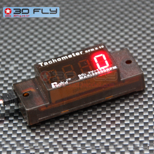
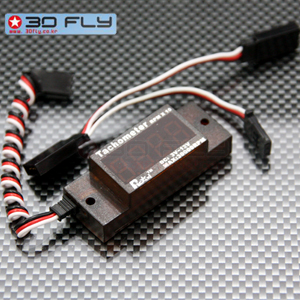
Ignition Mini tachometer Ver 3.0
상세정보 새창 열기
상세 정보를 확대해 보실 수 있습니다.
Ignition Mini tachometer Ver2.[Hard Case]
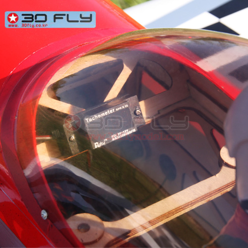
이그니션과 홀센서 사이에 끼워 실시간 엔진의 RPM를 Check 하는 획기적인 ITEM입니다.
전자방식으로 정확한 측정이 가능합니다.
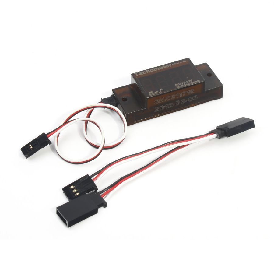
(전용 Y코드는 포함되어 있습니다!).
상품구성:
-Ignition Mini Tachometer :1개
-Y코드:1개
주의사항:
-DLE엔진 및 OS엔진등, RCXEL사의 이그니션에만 사용가능합니다.!
상품상세설명:
1. Use PIC16f628a microcontrollers
2. Do not need batteries,Power from the ignition
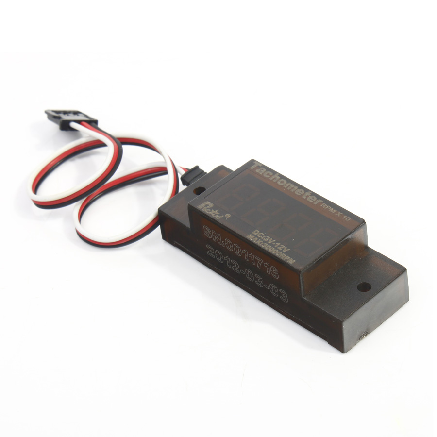
3. Standard FUTABA plug(Black-Negative Red-Positive and White-Signal)
4. Using high-brightness LED digital tube.
5. 입력전압 :3.5V-12.0V
6.전류소모량: 25mA-60mA
7. Mini tachometer indicates up to 30000 rpm
8. Actual RPM= Display Digital *10
9. 전체사이즈: 41mm L x 17mm W x 12mm H
10.액정사이즈: 30mm L x 15mm H
11.무게:8.5g
2. Do not need batteries,Power from the ignition
3. Standard FUTABA plug(Black-Negative Red-Positive and White-Signal)
4. Using high-brightness LED digital tube.
5. 입력전압 :3.5V-12.0V
6.전류소모량: 25mA-60mA
7. Mini tachometer indicates up to 30000 rpm
8. Actual RPM= Display Digital *10
9. 전체사이즈: 41mm L x 17mm W x 12mm H
10.액정사이즈: 30mm L x 15mm H
11.무게:8.5g
Instructions:
1.The Y wiring tandem between in the HALL sensor and the ignition.
2.The tachometer plug the other end with Y wire.
3.Connected to ignition power supply and can be displayed
2.The tachometer plug the other end with Y wire.
3.Connected to ignition power supply and can be displayed
Note:
That connecting plugs do Reinforcement. To prevent vibration.
The hall sensor & tachometer wire Leave from the Ignition high-voltage wire,
And receiver wires over 30cm
That connecting plugs do Reinforcement. To prevent vibration.
The hall sensor & tachometer wire Leave from the Ignition high-voltage wire,
And receiver wires over 30cm
Connection tachometer is not recommended after the use of flight,
Best to remove the Y wire to restore the original sensor connection
Best to remove the Y wire to restore the original sensor connection
If ignition have an additional tachometer pinout.
You must be connected to dedicated tachometer signal wire.
You must be connected to dedicated tachometer signal wire.
Note:
Can not guarantee that other types of ignition can use the tachometer And guarantee accuracy